“We believe that electricity exists because the electric company keeps sending us bills for it. But we cannot figure out how it travels inside wires.” — Dave Barry
The fundamental laws of electricity are mathematically complex. But using water as an analogy offers an easy way to gain a basic understanding.
Electricity 101 – Voltage, Current, and Resistance
The three most basic components of electricity are voltage, current, and resistance.
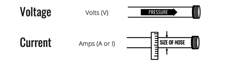
- VOLTAGE is like the pressure that pushes water through the hose. It is measured in volts (V).
- CURRENT is like the diameter of the hose. The wider it is, the more water will flow through. It is measured in amps (I or A).
- RESISTANCE is like sand in the hose that slows down the water flow. It is measured in ohms (R or Ω).

Voltage, current, and resistance are all related. If you change one of them in a circuit, the others will change, too. Specifically, voltage is equal to current multiplied by resistance (V = I x R). Thinking about water, if you add sand into the hose and keep the pressure the same, it’s like reducing the diameter of the hose… less water will flow.

Electricity 201 – DC, AC, Batteries, and Transformers
How does electricity work in electronics and the grid?
DIRECT CURRENT or DC is similar to the normal flow of water in a hose – it flows in one direction, from the source to the end. Historically, DC was originally championed by Thomas Edison in the famous Current Wars of the late 1800s. DC lost the war for the grid but it has found an even more exciting role in modern electronics like computers, phones, and televisions.
[elementor-template id=”16141″]
ALTERNATING CURRENT or AC is like the water flowing back and forth within the hose many times per second. The water analogy breaks down a little here but AC is easily created by electric generators (also called alternators). Nikola Tesla and George Westinghouse championed AC over DC and they eventually prevailed. AC is now the global standard for delivering electricity to homes and buildings via the grid.

BATTERIES can be thought of as water pumps that circulate water through a hose that travels in a closed loop back to the battery. There are many metrics used for the capacity of batteries and not all are immediately logical. They include amp-hours and kilowatt hours. Batteries can only generate DC power.
TRANSFORMERS are like holding your thumb partially over the end of the hose to get the water to spray farther. The water volume (power) remains the same but the pressure (voltage) increases as the diameter (current) decreases. This is exactly what transformers do for overhead powerlines. The electricity can travel farther with fewer losses because the resistance (sand) doesn’t impede the electricity (water) when the current is lower (smaller diameter hose). Transformers only work with AC. The ability to move electricity over long distances is the main reason AC beat out DC a century ago.
Electricity 301 – Power and Energy
Now, let’s keep using the hose analogy to dive into the murkier waters of circuits (pun intended, sorry).
POWER is like the volume of water that is flowing from the hose, given a specific pressure and diameter. Electric power is measured in watts (W). And larger systems are measured in kilowatts (1 KW = 1000 watts) or megawatts (1 MW = 1,000,000 watts).
ENERGY is like measuring the volume of water that has flowed through the hose over a period of time, like filling a 5 gallon bucket in a minute. Electric energy is often confused with electric power but they are two different things – power measures capacity and energy measures delivery. Electric energy is measured in watt hours (wh) but most people are more familiar with the measurement on their electric bills, kilowatt hours (1 kWh = 1,000 watt hours). Electric utilities work at a larger scale and will commonly use megawatt hours (1 MWh = 1,000 kWh).

Hopefully, this offers a helpful introduction to the basics of electricity. We’d love to hear your feedback and suggestions, so please leave suggestions and comments below.
Leave a Reply